Holy crap! I am actually working on my own CRX! I'm scared and excited. The first day of major surgery went pretty well.
So, here is where I started off. Well, sort of. I removed a bunch of stuff before and moved the radiator support out of the way to make my life easier:
 I sprayed everything down with liquid wrench:
 I like Liquid Wrench. It foams up and seems to "stick" pretty well, without just running off/away.
I got the clamps off the filter next . . . but man, that this is literally wedged in there:
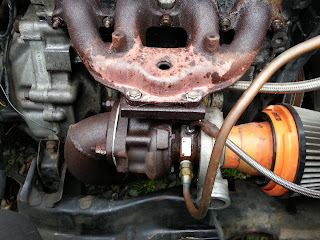
 This is why I don't like using copper lines, especially for coolant:
 That being said, I still prefer hard lines to the braided stainless lines everyone seems to love so much. When I re-do these lines, I will be using annealed stainless steel brake lines. No rust, no breakage, no leaks, and they look good on top of it!
Data plate on my cute little turbo:
 Made in Japan, just like my CRX!
Ready to attack the bolts:
 Notice I used stainless bolts. I love stainless hardware.
Here is the very first exhaust piece I made entirely myself:
 That is a genuine 3" downpipe off the T25. Talk about overkill, but I wanted to minimize spool times, and I sure as heck did!
Ugh: reminders of a super annoying repair I had to make on this engine from the one time I let a friend take care of my car:
 Stu: You suck sometimes.
And another reminder:
 I'll be fixing that when I take care of something for the front crossmember, too.
Well, everything was going pretty smoothly! I even managed to get the O2 sensor out without an issue:
Yeah, that is really tight:
 You have to thread the nut on before sliding the flange home.
This was no ideal, but still a pretty good drain angle:
 I never had any issues with it at all, but have something a bit better in mind for when everything goes back together again.
And then, a thunderstorm rolled in HARD. Ihad about 1 minute of warning when the wind shifted and a few fat drops of rain started coming down. I knew what was about to happen, so I jammed my tools under the hood, threw parts back into my trunk and barely made it into my Legend before the sky opened up.
I sat in my Legend for 45 minutes to this view:

After the storm had passed, I got back to it and managed to get the turbo out completely:
 Here are some of the things I need to rectify for the next version:
 SOHC exhaust manifold gasket, not even ported to fit! LOL!
See how much overlap there is up top?
 Yeah, athat can't be good for anything, so next time, I'll be using proper DOHC parts and port-matching the manifold itself.
After the rain, I was too wet to really take too many pictures, but there wasn't too much more interesting that happened aside from me discovering that I need a new brake booster since I couldn't separate the master cylinder from the brake booster due to the MC leaking fluid and corroding the booster pretty badly.
I am ordering an Hf booster to replace this one, as it is physically smaller. I will need the extra clearance for running my Edelbrock manifold when it gets swapped into the car.
So, not a bad start to work, even if I didn't get as far as I would have liked. That's OK. I'll be back after I get the booster so I can get that replaced and get on with the brake R&R. I have new calipers rotors and pads for the front. I won't be messing with the back at all as long as there are no apparent issues in use, and I don't really anticipate there being any, either. Eventually I will replace the rear wheel cylinders for good measure. No, I am not swapping to rear discs, as I despise the Civic/Integra/Whatever integrated parking brake caliper. It is a piece of junk design and I hate it. I will only ever swap over to rear discs if I can find a way to install proper rear discs that uses a disc over drum setup for real parking/emergency brake use. Rear drums work better for that kind of thing, and since my car is so darn light, the rears don't do much for braking anyway.
So, here is where I started off. Well, sort of. I removed a bunch of stuff before and moved the radiator support out of the way to make my life easier:


I got the clamps off the filter next . . . but man, that this is literally wedged in there:


Data plate on my cute little turbo:

Ready to attack the bolts:

Here is the very first exhaust piece I made entirely myself:

Ugh: reminders of a super annoying repair I had to make on this engine from the one time I let a friend take care of my car:

And another reminder:

Well, everything was going pretty smoothly! I even managed to get the O2 sensor out without an issue:

Yeah, that is really tight:

This was no ideal, but still a pretty good drain angle:

And then, a thunderstorm rolled in HARD. Ihad about 1 minute of warning when the wind shifted and a few fat drops of rain started coming down. I knew what was about to happen, so I jammed my tools under the hood, threw parts back into my trunk and barely made it into my Legend before the sky opened up.
I sat in my Legend for 45 minutes to this view:

After the storm had passed, I got back to it and managed to get the turbo out completely:


See how much overlap there is up top?

After the rain, I was too wet to really take too many pictures, but there wasn't too much more interesting that happened aside from me discovering that I need a new brake booster since I couldn't separate the master cylinder from the brake booster due to the MC leaking fluid and corroding the booster pretty badly.
I am ordering an Hf booster to replace this one, as it is physically smaller. I will need the extra clearance for running my Edelbrock manifold when it gets swapped into the car.
So, not a bad start to work, even if I didn't get as far as I would have liked. That's OK. I'll be back after I get the booster so I can get that replaced and get on with the brake R&R. I have new calipers rotors and pads for the front. I won't be messing with the back at all as long as there are no apparent issues in use, and I don't really anticipate there being any, either. Eventually I will replace the rear wheel cylinders for good measure. No, I am not swapping to rear discs, as I despise the Civic/Integra/Whatever integrated parking brake caliper. It is a piece of junk design and I hate it. I will only ever swap over to rear discs if I can find a way to install proper rear discs that uses a disc over drum setup for real parking/emergency brake use. Rear drums work better for that kind of thing, and since my car is so darn light, the rears don't do much for braking anyway.


.jpg)


