Tag Line

"Built Dam Strong!"
Showing posts with label turbo manifold. Show all posts

16 March 2014

Pete's Turbo Manifold: More progress, finally.

After much too long a hiatus, I got back to welding up Pete's twin scroll manifold. I made pretty significant progress, especially thanks to being able to use a lathe!

Of course, pics are the thing you come for, right?

On thing I see on some manifolds is poor access to the flange nuts. If you're making something yourself, why make things hard to get to? How do you figure out how much space you need? Simple. Use a tool as a spacer:
 Once that was figured out, I got the pipes lined up on the flange and started welding them together:

I finally got to use the torch a friend sent me to try out:
 It's different. I'm not sure if I like it yet. It works. I'll keep using it.

Now for something totally cool! My friend recently acquired a new South Bend Heavy 10 lathe. Seriously. New. New as in it had the original cosmoline packing grease on everything and he had to put it together himself! If you don't know about these lathes, they are one of the most desirable classic benchtop lathes, and after using it, I can see why. I'm really surprised by the quality of work it can do for being such a compact machine!

Anyway, my friend turned a chamfer on some straight sections of pipe while I cut stuff:
 Look at how nicely that matches the 90* fitting!!!!

Got everything tacked up:


I started welding the straight pipe to the bend:
 I'm getting some advice from my friend who sent me the torch I'm using. Stainless is a pain to weld, and I find this thicker stuff tricky. I love learning this stuff, though!

Here's how I'm figuring this should go together:


 I made the straight sections a bit too tall, though, so those will need to get trimmed down. This manifold is going in a 1G CRX. It has very little room in front of the engine, so I am trying to make this whole thing as compact as possible while still being a decently flowing manifold as the power goals for the built are 500+WHP.

I'm looking forward to moving this along. I really enjoyed

28 August 2012

Progress on Pete's Manifold

After a super busy day, I got in some more welding. I am starting to get the hang of welding this thick stuff. I have resolved that I need to get some slightly thicker filler metal as the thin stuff I have now is melting back too fast for me to keep up a good rhythm. I'm still improving and will keep it up!

I start out with cleaning. I used acetone to get the residue from the sticky foil tape off the merge pipe then sanded it with sandpaper on the outside and a cartridge roll on the inside. The inside needs to be cleaned, too!


I was tying to make my life easy but clamping this in my vise:

But I realized I really didn't want to try grounding the whole thing through precision machined jaws. I also totally forgot that the el needed to be cleaned up, too!

After I took it apart and cleaned up the 90* el, I changed game plans and got my (still less than ideal) purge setup installed and let the gas flow!


Here's a close up of the clean up:
I tacked the pieces together, checked fitment. Again. And again.  And then I got down to welding!

I'm starting to get the hang of it:

When I was wrapping around the sides, I ran into some undercut:


 I will fix that for sure, but after I tack the other side together. I was starting to scorch the blue tape holding the joints together on the other side. I'd rather they not come apart just yet. LOL!

More undercut to be fixed:

After the other leg is tacked up, I'll finish welding that section together.

Why do you backpurge? To get a clean inside joint, like this:
No, it isn't fully penetrated, but there is no "sugaring" of the backside which is basically oxygen contamination that will eat away at the stainless from the inside out, especially when exposed to very high temperatures found in it's intended application! 

24 August 2012

Pete's Twin Scroll Manifold Progress

Today was a busy day. It might not look like I got a whole lot done, but, when you are working with a tough material (Stainless Steel is a heck of a lot tougher to work with, and tough to work with correctly) in a new format (I've never worked with schedule 40 bends and pipe before), you have to go slow and take your time to get things to fit well in a manner that will flow well, especially when it comes to turbo setups.

Enough whining! On to pics!

The last time we saw stuff for Pete's manifold, I had made a few important cuts. Here's a refresher pic:


I couldn't take a lot of in process pics, but this is what I ended up with after way too long a time getting these two pieces to fit together in a decent low angle merge:


As you can see from the light leak, it isn't a perfect fit:


But looking at it from the important side (the inside):


 After a bit of cleanup, both legs are going to flow very, very nicely!

Once I got the pieces fitted up decently, it was time to clean everything up in preparation for welding. I use my hanging grinder (click HERE for more info on which grinder I use) and a roll cartridge that was fresh and never used on anything else. Here are the results:

A closeup of the texture left:

Then it is time for some really deep cleaning:

Use gloves!

Acetone is really nasty for your body. It absorbs into your skin and is not a good thing to force your body to deal with. Also, the oils from your skin can contaminate the weld and lead to rusting. No, that is NOT an exaggeration. Some people's skin oils and salts can leave rusty fingerprints on stainless.  It isn't a fun thing to see on your otherwise shiny stainless parts. LOL!

To wipe everything down you can use clean rags or paper towels, but I don't have rags, so I just use:

Remo (a guy I know) is going to kill me for not having a diffuser on my purge hose . . . but I haven't made one yet. LOL!


This turned out to be a bad idea. LOL! The hose started melting once I got to welding.

You can't block off all the piece. You need a place for the air (and specifically Oxygen) to escape as the argon fills the pipe. So, make sure you leave some place for it to come out at the very top of your workpiece!


I really need to make a "third hand." Check out this video by Jody at weldingtipsandtrick.com did to show his improved "third hand:"


The back side is taped:


I tacked it on one side, then taped that side up:


I had to smack it with a hammer to get the pieces to line back up. If you have never welded on stainless . . . you have NO idea how much that metal can move. It is CRAZY!

Since I had my hands occupied, here is the finished piece:

Most of the discoloration outside of the actual weld is the residue from the tape. The manifold is going to be sandblasted in preparation for ceramic coating, otherwise I would be a bit more attentive at cleaning that stuff up. Pete evidently likes to shift dirty things, so this is my little bit of payback. (JUST KIDDING, PETE! LOL!)

Weld closeup:

Since the fitup isn't perfect, the beads aren't really all that wonderful looking. This is the first time I'm welding this stuff and I'm no dummy so I starting with the pieces that are hidden in the back out of site. LOL!

I had a heck of a time figuring out how to mock up the rest of the stuff since I have two hands and the clamps that I have, while useful, aren't exactly wide enough to completely support the weight of the pieces of this manifold. So . . . I got creative:

I found some tube that slip fit into the straight pipe very snugly. I discovered that the ID of the els isn't exactly the same as the ID of the pipe, so I had to get even more creative and cut out a slice from the tube an ended up with this:

Which allowed me to do this:

And that is how I ended the night. =) 

17 August 2012

Pete's Manifold: Slow and steady!

Yesterday, I got the first cut made. Today, I got the start of runners #2 and 3 mostly done. 

A lovely package came, too. In it was more laser cut flange goodness!


Those are the entry flanges that conform to the T3 twin scroll "standard" from Garrett. I have yet to fit them up to see how exact they are, and as with anything like this, there will need to be some adjusting for everything to fit perfectly together, but they honestly look darn close. Chris, who does this for me does excellent work. If you need flanges done, hit me up and I'll give you his contact info!

So, here's what happened with the pieces I cut yesterday:

I found some really useful hose clamps at Pep Boys when I was shopping for Chrysler crap:

 They are made by Ideal, and yes, they aren't as cheap as normal hose clamps, but, when you don't have to use a tool to tighten them up, they sure are more convenient to use.

I started cutting the straight pipe for the runners:

 The angles look funny because nothing is sitting correctly since I haven't cut he straight section from #3 to fit onto the runner from #2. This is a nice, low angle merge that will flow well and create very little turbulence. Now cutting and shaping that straight leg to fit is going to be monstrously hard to do with the tools I have, but, I will certainly make it happen.

I am going to finish mocking up the #2 and 3 merge and upturn before I handle #1 and 4. Notice the pairing of 2-3 and 1-4. This is the correct way to merge a twin scroll setup, with exhaust pulses 180* off, basically out of phase. When coupled with a twin- or divided-scroll housing on a turbo, this allows for a much more efficient system that will spool faster and allow wilder cam profiles since there is a significant and beneficial increase in the pressure ratio between the intake side and exhaust side of the engine. This is very important since the turbine wheel forms a huge restriction. Nearly anything that can be done to increase the pressure ratio by lowering the exhaust pressure is a very good thing since it allows the engine to breath in more clean, compressed air/fuel mixture, much like a properly built and tuned header. Hmmmmm . . . I wonder where those ideas came from? heh


The first cut is the hardest. (Not necessarily the deepest . . . )

As an aside from the really gross crap I'm dealing with the rest of my day, I took a break and made the first cut in what will be many for Pete's custom twin scroll turbo manifold.


The manifold is being made from 1.5" Stainless Steel Schedule 40 pipe and bends (also knows as weld els, short for elbows). In the above pic, you can see that I cut a 45* cast elbow in half (it is very nearly actually a perfect cut). I forgot to grab a pic of why I did this, but basically, I wanted to minimize the transition angle between two runners of the exhaust, in this case, #2 and #3, and make accessing the bolts for the flange and engine mount easier. This leads me into thinking I really need to write up an article on handling and welding Stainless, as it is far, far different than dealing with normal steels, even to the point of requiring special markers so as to prevent corrosion.

I spent a bit of time cleaning up the saw cut, which you can see the "as cut" finish here:

 And here is the finished part:

Why go through the extra step when the saw cut is fine? Because Stainless. The basics of Stainless are:

PREPARATION! A good plan solves many issues before they start.
CLEANLINESS! It is NEVER too clean.
FITMENT! Perfect is not an option.
BACKPURGING! If you want it to last.

I'll definitely have to work on an article . . . And I just added that to my to-do list for next week. 

29 May 2012

PVC and Biiiiiiiiig sharpies . . .

Every once in a while, I'll find out how badly I've been stuck under a rock. Case in point: 


The Sharpie Magnum. I was at Home Depot picking up supplies for the next project, and while I was walking through the tool aisle looking for blue Sharpies, I laid eyes upon the biggest, baddest and most awesomest Sharpie I have ever seen! I just had to get one and see what it was like; if it could fulfill my every dream of marker perfection!

In that regard, it isn't and doesn't, but it is certainly super useful. The Chisel tip, as you can see below is really well designed allowing you to mark a HUGE swath, a BIG line or a PRECISE mark just depending on how you hold it. 


If I find out that they make this thing in blue, I'll never buy another type of Sharpie again!

Now, here's a pic of what I was working on today:


I mostly used my camera, file, sharpie, machinist's rule, mini tape measure, a reciprocating saw (off camera at the time) and the PVC bits. The black bag is full of magic, though. It's one of my most useful sets of tools. LOL!

So, what is all the stuff for? Mocking up Pete's twin scroll turbo manifold! If you recall the picture I posted a while back of the really nice looking GT3076R? Well, this is the start of a manifold for that!

Pete and I decided that a Schedule 40 1.25" pipe would be the best bet for the manifold, but, I was doing some math and I found out that 2" schedule 40 pipe has nearly the same CSA (cross sectional area) as two of the 1.25" pipes. Since this is going to be a twin scroll manifold, why not keep the CSA constant after the primary merge? So, that is what I am going to attempt to mock up in PVC, since it is cheap and easy to work. 

Lets get to work! First up, knocking down all the casting ridges on the PVC, as you can see here:


Now you might ask yourself, "Self, why the heck is he bothering doing something as anal retentive as that?" The answer is pretty simple! Taking care of those ridges will allow the fittings to fit flush, in necessary, which will make measuring and fitting more accurate and precise. Granted using PVC isn't exactly the most accurate way to build a template for this, but, I am mostly using it as a good visual aide   an to figure out approximately how many bends and how much pipe I need to buy in order to finish a manifold of this sort. This will ultimately lead to a more succinct design process with less overall headaches, even if some of the dimensions change. This will also allow me to see a real, physical model in 3D, and hopefully will allow me to package the whole thing much tighter as a result, which is a huge concern given how tight the engine bay is of the car this whole mess is going to go in to. 

After I filed down the casting flash, I started making some spacers to hold bits and pieces together:


 I won't be gluing things at all, so I made sure to keep the tolerances pretty tight for these things. Holding a tolerance of under 1/32" with a reciprocating saw is pretty effing good, I'd say. I also cleaned up and deburred the rough cut edges and kept everything as flat as possible.


This is the kind of fitup I am after:

The spacer is nearly perfectly snugged to the cast in edges of the elbow.

Everything fitting together superbly:

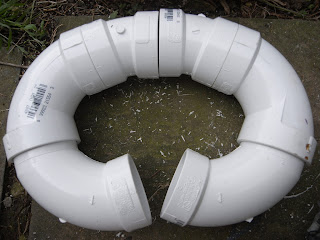
The main U is made from one 2" street elbow and one normal elbow.


 The upper part is a 22 1/2"* elbow, which I like very much and may get some in the 1.25" size, also, to keep turns nice and easy for the trickier bits of running the inner (2nd and 3rd cylinder) primaries to their merge. 

Here are the ready to experiment secondary pipes:


 As always, more to come in the next few days! =)