Tag Line

"Built Dam Strong!"
Showing posts with label CB450. Show all posts

23 May 2012

Cardboard conundrum, or Poor Man's CAD

Today I spent some time getting down and dirty with cardboard. If you're on the internet, I am pretty sure you've heard about CAD, or Computer Aided Design. It's really rad and all, but, for many people who build stuff, it is still out of reach other price wise for software, or, in my case stupidity. (I've never learned to use any of it.) There is another alternative, however, that works better for many people, especially if you like to get hands on and try to make things work, or, if you have something that you only need to make one of and that one thing has to fit on something that wasn't made with particularly tight tolerances, like Mike's bike, for instance.

I will say today was semi-embarrassing. Well, it is only embarrassing if I tell you about it, which I am going to so that makes it embarrassing. What shouldn't have taken more than a couple of hours took me all day. Being out of practice sucks, and not being with the tools I am normally accustomed to have to aid me in my pursuits. Enough excuses, on to pictures!

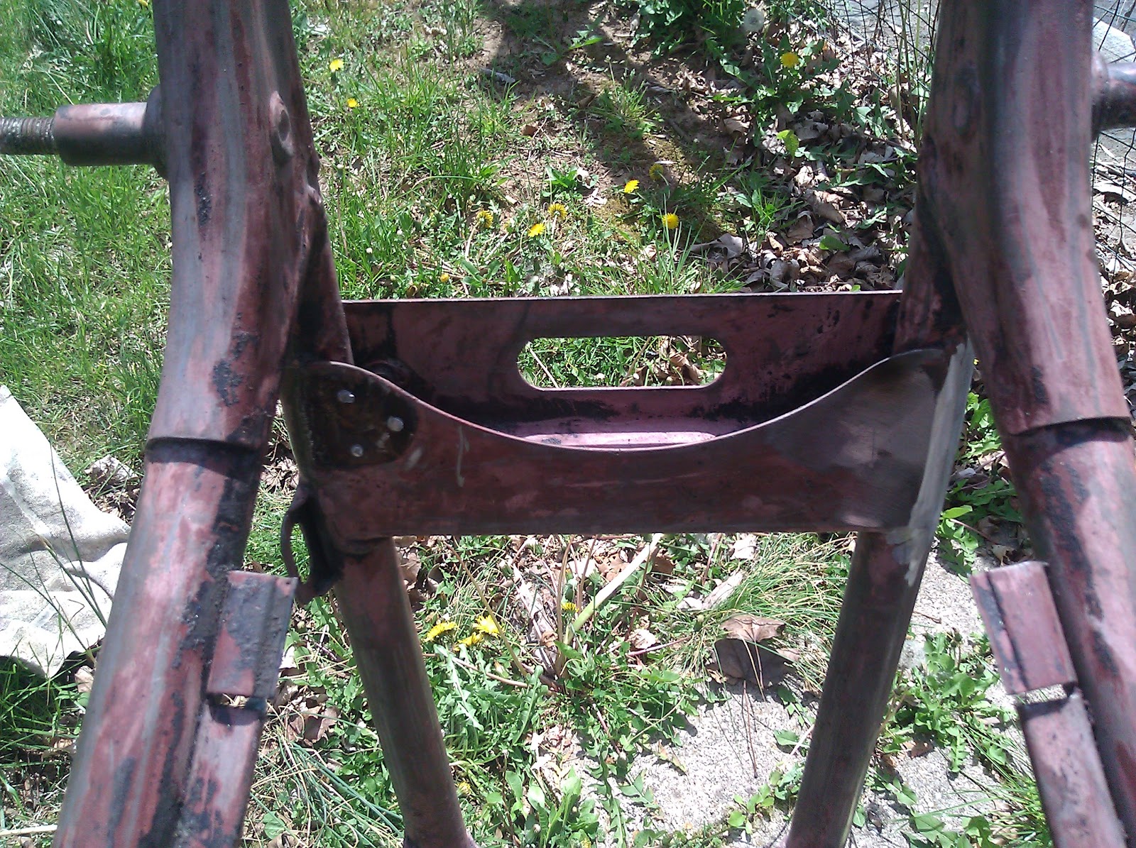
I started with the battery tray, since that needed to be set at a depth that would allow for a maximum of 60mm or so for the battery and electronics:


This also led to the first of many revisions to my measurements. The gap you can see on the sides of the straight up and down piece were too great and with the next version, I tightened that up considerably. 

Lots of scribble, lines, and mistakes that all get confusing:


But, after cutting the right pieces out, I end up with this:


Very minor profile! The gap there is from the thickness of the cardboard hitting the brackets. I might have to make a slight trim on the actual metal, but it is nothing more than about 4 seconds with a cutoff disc won't cure. 

Here's the interior of the battery tray:


Plenty of space for whatever Mike wants to stuff in there. 

Here is a view from the other side: 


I didn't get a lot of in-progress pics for the next part because I was busy and email cell phone pics to Mike to clear up some concerns I had with how things should fit around the tank. 


One of the reasons why it took so long to do was that I discovered that with the tank in place, it was impossible to get the seat pan as close to the tank as Mike wanted while having the top of the seat be completely flat, as if you look from the side, there is a lip that comes off the back of the tank. So, I raised the front support for the seat (I didn't grab pics of that, oops) by a 1/4" and that gentle slop raised the front of the seat pan enough to clear the tank. Also, in the side view pic above, I had to slowly trim back the front of the side sections in order to clear the lip. Lots of back and forth and fit and test and cut and draw and cut. LOL!

Before I get too far ahead of myself, I should explain a bit more about what is going on. Mike wants the seat low and lean, to keep the lines of the bike flowing with minimal visual interference. The custom hoop that I installed a few days ago is part of that design. Looking, well, staring at the bike when I first got it, I saw a natural break in the supports for a seat pan. What I envisioned was making the front section (as you see above) then making the rear section (as you'll see following this mess of text), joining them together at their vertical supports in the middle. This would make the seat stiffer and the metal easier to handle. (Separate pieces are easier to move around, cut, form, drill and weld on than larger, bulky and floppy pieces.) With that being said, it's time to move on to more pictures.

This is a support I made for the template:

The longer piece that is inline with the frame is not going to be in the final seat. I just make it to prevent the cross-brace from falling over. heh 

There was a huuuuuuge gap in pictures again, but here are the final ones:


My brain is so rusty. It took hours to figure out the rear section. What happened was I wasn't using the correct radius for the ID of the bent tube for the hoop. I was using the centerline radius (4") instead of the ID radius (3.75"). UGH! I wasted a lot of cardboard and time. BUT . . . I got it figured out!


I don't have a ring roller (yet) so rolling that ring for the rear of the seat is going to be tricky. I have something I want to try with my newly acquired bead roller (thanks again, Mike!) to mimic a bead roller. Since I am only dealing with 18g steel, I think it will work. Time, and this blog, will tell.

Side view of everything mostly in place, though not everything is seated as it will be:


And the final pic for the evening:


As much as this was a pain in the butt, I really enjoyed the work, even the frustrations of it. My brain was actually working (though creaky and in need of lots of WD40). It is so hard to describe the joy I get from doing this kind of thing, and that is why I want to keep doing it, constantly improving in everything I do. I love these kinds of jobs, as I get to learn-relearn, improvise, adapt, overcome and ultimately bring something into this world that was previously only a dream or a sketch or a thought or simply a desire. Mike said "I would go so far as to say I'm alarmed at how perfect that seat is to what I envisioned." That's the kind of work I try to do.

Now let's see if I can translate that mess of tape, cardboard and pen lines into a functional version in metal that will be enjoyed by Mike and probably his wife. I can't wait! =) 

19 May 2012

Due to my injury yesterday, I slept in and had a lazy beginning to my day in my apartment. During the night my cut knit together well. I think the scaring, if any, will be minimal Yay!

I finally got up and out in the afternoon and proceeded to get busy!

Here is a look at the right side of the tail of the frame and the hoop I was working on yesterday:


I shortened up the extra length until the frame rails matched up as closely as I could make them without having something along the lines of a ring roller to correct the radius. What's a fellow to do? Well, with a bandsaw, extra material from the legs I cut down and a welder, there isn't much I can't do!

I sliced a short section of the tube in half and then formed it around the tubing using my handy vise and hammer:


Here is what I ended up with:


The other half I actually squished down until it fit on the inside of the fram rail, then tapped it into place thusly:


Since I had a severe lack of assistants floating around (because I am knee deep in assistants usually. HAH!), I had to use what is left of my brain to hold the hoop in place. When that was shown to be futile due to the fact that brains are squishy and not very good at adhering metal together against the forces of gravity, I found a ratchet strap and used it to lock the hoop into place:


The zip ties are there to keep the strap from slipping off the sides and dropping the hoop as I tapped it into place with the hammer for the next phase of global domi . . . working on Mike's frame. 

The next picture is a bit blurry, but you can clearly see the frame is not exactly round and not lined up as well as I would like:

Here is what I use the other half of the tube I cut up for:


That should fill the gap nicely! I trimmed pieces down and fit them up better, tacked everything into place and then started a lot of welding:


As you can see, I basically covered everything in weld building everything up as smoothly as possible:


It took a while to weld all that in, but I think I did a really decent job! It took about 5 whole minutes with a flap disc to clean it up and get it to look like this:


Not too shabby at all!

I even managed to keep the hoop pretty dead flat with the rest of the frame! 


That is going to make finishing the measurements and eventually the fitup for the seat pan very easy. I like easy, at least when it works. LOL!

Oh! And one last thing:


What hole? Doesn't look like there was every a hole there. =) 

18 May 2012

Wear your effing safety glasses/goggles/shields.

After a late but very productive day yesterday, today started off bright and early with a good breakfast and running a few errands. After getting that stuff done, I header over to the "shop" and set to work.

I had noticed yesterday that the bandsaw wasn't exactly set very perpendicular to the work table, so I got out my square and got it as close as I could. Then I cut four 1.5" long pieces of tube:


They turned out really decently with the adjustment! Also, as a side note: ALWAYS DE-BUR YOUR WORK! Always. It saves your fingers and makes fitup a lot better overall. 

Those four pieces are going to be slip fit collars for a collector:


The reason for doing it this way is that the steel is good quality and thick enough (16g) so that "normal" tailpipe expanders cannot actually expand the metal enough to make slip fit joints. This is HIGHLY annoying to me. My good tailpipe expander is even too large to fit into the tubing of that particular collector, so I am forced to try goofy things like this. The hardest part will be welding the insides, though I am likely going to cheat and MIG those parts since even my small TIG torch can't really reach in too far and the pieces will need to seal. 

Once I finished those up, I moved on to the next task: removing the motor from my Che-ese drill. (Che-ese = Cheap + Chinese)


I've had this thing since 2003. It stopped working last summer. I figured that the cheap motor just died. No biggie. I'd take the motor to an electrical supply store and get a new one that is likely way more torquey than the old one. Well, that wasn't the case. I pulled the switch plate off and was looking at the wiring, figuring that maybe something had come loose, since, after all, this is a Che-ese drill, and something could have fallen apart. Poking around the innards, I found wiring that didn't make much sense. How hard can it be to wire in two three-wire wires? (Hot, neutral and ground, the modern wiring standard for AC electrical supply.) Well . . . after a few minutes of probing the switch and wires with my multimeter, I was convinced that the darn thing hadn't been wired correctly from the beginning. I switched two wires around and the motor spun up better than ever! Now the only question that remains is how the heck did it work for 7 years with the wiring screwed up? That is some Chinese magic, no doubt. 

I spent a good bit of time sharpening tungsten after that. Talk about mind-numbing activities . . . I mean, it is involving. You have to angle the tungsten correctly, rotate it at the right speed and hold on to it without letting it bounce too much on the stone. What's worse is that I was starting from scratch with 10 brand new 1/16" electrodes. You might think that thinner would be faster, but that isn't the case, because you can overheat them much more easily so you can't apply as much pressure as you would a thicker tungsten.

I haven't used any electrodes so thin before. I am kinda of excited to see what difference it will make when welding the thin tubing and sheet I am going to be concentrating on over the next week!

The afternoon progressed into early evening. I started up on another piece to a puzzle: the rear hoop for Mike's CB450 frame. He bought a pre-bent hoop that was mostly the right width but with legs that were too long. That isn't an issue with a bandsaw around, though. =) 

As I mentioned a moment ago, the hoop was mostly  the right width and I wanted to spread the legs a bit wider to neaten up the transition as much as possible so I can save myself some work and make things look cleaner all together. 

Here's the hoop in the vise:


I simply used the vise to act as an expander.


With the extra length of the legs, I got the hoop to open up a bit, but the material sprung back quite a bit. I shortened the legs up just past the first bends and started to slowly expand the hoop which worked brilliantly. 


I was taking it very slow, working the hoop a little at a time, since too much too fast is NOT a good thing when trying to maintain a nice, mandrel bend. 

Until . . . the hoop sprung off the vise so fast i couldn't even react and it hit me in the face. Specifically, it hit my right eye lens of my safety glasses and smacked my lip pretty good, too. The impact was so intense, the edge of my safety glass lens sliced open my cheek like a shear, thusly:


My face hurts. I cleaned up the cut and put the butterfly on it. I know I am going to get fussed over when "normal" people see it (especially a certain woman), but it'll be fine eventually. After I got it cleaned up I tried on a different set of safety glasses and my nose promptly protested enough to tell me to call it quits for the evening. 

The whole point of this is that I would be out an eye, or, look like I lost a fist fight if I had not been wearing my safety glasses. WEAR THEM. You are beyond foolish is you don't. Wear them before you start working. Keep them on at all times. Don't take them off until all your tools are at least at rest and nothing is under tension or stress. 

Final pic of the evening:


The angle of the camera lens throws the perspective off a bit, but the hoop nearly matches the outside of the frame rails. This will be much easier to fit up once I trim the legs to match the profile that Mike wants, which is basically as short as possible to enhance the lines of the bike.

01 May 2012

New things and projects to come!

Mike and I went out today to pick up the sheetmetal and some other stuff for his bike. He also dropped off this rear hoop that I will be chopping and fitting into place:


It's not exactly the same width, but I will be taking care of that easily enough. 

Boxes can be fun!

This is certainly not a cheap collection of "presents" inside those boxes, though! 


Garrett GT3076R, .78A/R T3 flanged twin scroll V-band outlet turbo and two TiAL wastegates. I have to say, the fit, finish and precision of the TiAL parts is some of the best I've seen on non-Military grade stuff. EVERYTHING from the fittings to the body fits perfectly and is made superbly from quality materials. I love seeing stuff like that! 
This project is going to be VERY tough. The compressor housing is HUUUUUGE. I need to tuck off of that and all the piping as close to the block as possible while NOT making it impossible to get to all the bolts, fasteners and lines (oil and coolant lines) needed to effectively run this setup correctly to maximum potential. I have some ideas, but, once I get the block mounted and a head in place, I'll be better able to visualize what needs to go where. 

This is my new workbench, a Harbor Freight special for $24.99. 


It is very worth it for the price, even if some of the holes were not tapped and I have to wait to get the rest of my tap and die set from home to finish bolting it together. It is actually fairly sturdy except for the really cheeseball "shelves" they give you. I will be making my own of plywood, using the original "shelves" as a template. 

Not fastened on yet, but perched atop the work surface is this amazingly awesome piece of metal:


I got this vise for free. It is likely older than I am. It had (has) some surface rust that I cleaned up and is not functioning amazingly. It weighs as much as the workbench (maybe more). It is overkill, for sure, and I know that the workbench would tip over if I apply too much torque to something, BUT it will work well enough for what I need it for (mostly to hold stuff while I work on it). There is nothing like a quality vise. =) 


Mike's frame

I actually got this work done . . . dang, a couple of weekends ago. I mostly detabbed some of the extra bits that Mike no longer needs, cleaned up some of the stock welds and welded the front forks around where they joined as I think that looks a whole lot better and should help strengthen and stiff the front up a bit over the factory plug welds.


The previous owner left this nice surprise:


That hole was actually filled with body filler and it looked pretty darn convincing from the outside. I am going to back the hole with some tubing that will slip fit inside then weld it closed and smooth it out. You won't ever be able to tell there was a hole there. 

Tricky bits to get to with a grinder, but I did it:


Right side completely smooth and left side ready for some flap disc lovin!


I also came up with the plan for the seat pan. I am actually going to be doing it in two parts, in order to provide for stiffness and flexibility since I will have to modify the design for the rear as Mike just got me the rear hoop and I will weld that in place before making any final calls on how the rear of the seat is going to look.


Battery tray plans:


Surgery!