So, last weekend I left off having gotten nearly nothing done that was planned and a whole lot of stuff getting done that was way out of any plan I could have made.
Wednesday, or what is Thursday? It might have been Thursday. Well, some day this past week, Dave came by and we set about repairing the broken wiring from the previous weekend's poking about.
Here is the rotary switch that is rotated when the directional control is selected:
 I think. I am still confused by this, so, you'll have to just ignore my confusion and let me ramble about this for a bit.
Here is a view of the side you can see from the access panel:

The gear position is important.
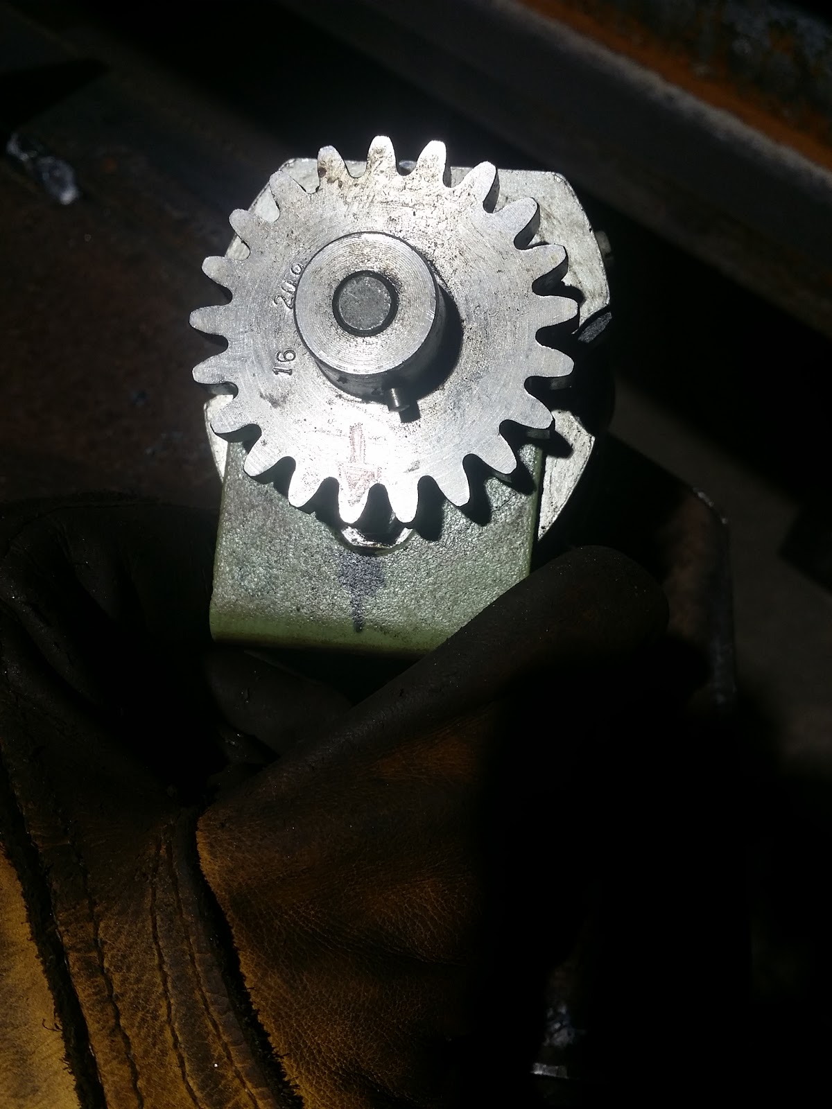 We found that out early on in this process. It's still not exactly right, but, well, that's the way it goes. heh
While I waited for Dave to show up after work, I moved the mill and started cleaning. Here is an in process shot of one of the access panels:

I was using WD40 and these EXCELLENT No Scratch Scotchbrite pads:
 Those things are REALLY good and, as their name implies, they do no scratch what you are working on . Brilliant!
After:

What wires go where? Hmmmmm. . .

Dave, hard at work poking at the wiring some more:

I still can't get over how far the table travels. That's just ridiculous.

At this point, we had restored power to the power feed, but still only in one direction. Dave and I determined that one of the four relays wasn't activating. I could feel it buzz when we moved the power feed switch to the opposing direction, but it simply wouldn't actuate. I figured that since it was already broken, I couldn't really do any harm if I tried to pull it apart and fix it. So that's what I did!
This is the offending relay:


 It's a pretty heavy sucker. It is certainly made to come apart, though, and has some pretty trick features that I'll show.
First things first, address the relay thusly: "Hello, relay!" Then pop the two spring clips that hold the top on and expose the upper contacts that tie in to the power wires on top:
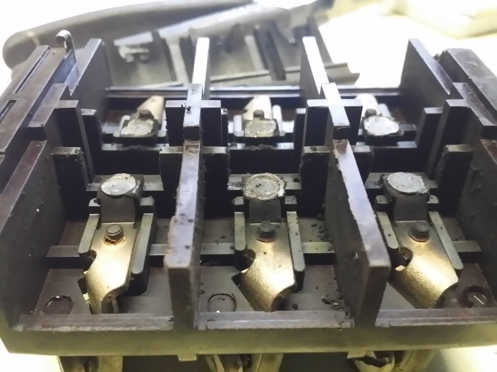 Um . . . What contacts? Geez. I think they are completely worn out, and with the carbon on top, it wouldn't have been able to pass current even if the relay had actuated!
These contacts are spring loaded and also extremely worn and coated in carbon:

The actual contacts themselves are not terribly hard to rebuild, since they easily come out:
 A small spring holds them in place. if I so choose, I can solder on a new copper button to the contacts, effectively restoring it completely.
I forgot to take pics of the rest of the disassembly, but with one more spring clip and four small screws, the rest of the relay comes apart as far as it can go:

This is the top of the core of the "motor" of the relay:
 I think that gunk on there just MIGHT be a problem.
This is the top of the motor core, which moves on a very cool cam system:
 When current passes through the coil (which I will show later), it magnetizes the core, which attracts the top of the core, moving the arms and allowing the contacts on the top of the relay to contact the tie in points. I love it!
After I cleaned the gunk off the top of the core, I noticed that from decades of use, the legs of the core had some pretty sharp edges:
 I filed those down like a good machinist would. I just used some electrical contact cleaner in a can and some fine sandpaper. It did a very good job of cleaning the gunk up without removing much material at all, which would effect tolerances, which I am sure are on the ragged edge for some pieces in this relay.
Here are two pics of the different positions of the top of the core. This first position is the "activated position" when then coil magnetizes the core and attracts the cap downward:
 This is the retracted position:
 If you compare them closely you can see the cantilever action employed to keep the cap pretty level through the length of travel. It's really very cleaver.
Here's the core all cleaned up and deburred:

Remember those really gunky contacts from before? Well, after cleaning they look better, but still are very, very worn:

The next pieces (I am not sure what they are called, but they seem to act as side covers and arc suppressors) gave me quite a shock. I thought they were all hard plastic until I blasted them with the cleaner and found this:
 That's a heck of a lot of carbon!
Here is the coil installed on the core:

And here I start reassembling everything:
 I honestly hadn't noticed it when taking everything apart, but everything on the relay that needs to be put back in a certain way is directional. It can't install it backwards!
The long spring clip that holds the motor assembly to the stamped steel chassis has flats ground in to the ends so that when you press it through, you can't pull the clip out without pressing the ends of the clips away from the periphery of the square hole they pass through:

Another view of the flats:

The bottom end reassembled:
 These ends of the long spring clip:
 The helper spring is then reattached at the back:

The contact spring bases are reinstalled on the top side:
 Then the springs are put in place:

The next part was a bit tricky, as I had to compress the spring (wear flipping safety glasses!!!) with a flat tip screwdriver enough to slip the lower contact piece into place:

Another few minutes later:

These spring clamps proved to be a right pain to put back in place:


After I got one of the spring clps in, I realized I had to put the side things back on:
 ARG! I undid the clip and put the side pieces back on, starting with the insulating backing plate:
 Then screwing it into place:
 And finally clipping the retaining clip into the armature so it would move with the contact plate:


DONE!

Actuating the relay by hand now had a much more positive feel to it. I was pretty hopeful this would solve the power feed mystery!
I got it put back into place and wired up:
 What happened? The power feed switch started working when switched in both directions! Except . . . that the power feed was moving the same direction. HAH! I flipped two of the wires on top of the relay and THEN had power feed in both directions. Still no fast traverse, but, I'll keep working on that.
Now that the power feed was working in both directions, it was time to make something, right? The first order of business was to make a spanner wrench for my two collet holders. I have only been able to hand tighten them up to this point (and I don't feel like spending a good amount of money to get a tool that has jaws wide enough to fit the collet collar), which isn't good as the torque spec for the collars is 75ft/lbs.
Time for another boring machining video! YAY!
I ended up attempting to get something workable three times. *shakes head* I am so out of practice milling things it isn't even funny. Whatever. At this point, I'm just happy to be able to make chips.
Here's the spanner wrench:


Yes, the endmill is discolored. So are quite a lot of chips:
 The lighting in the shop is really crappy for good color rendition . . . A lot of those chips are blue. That happened because I accidentaly set the power feed to about 10x what it should have been and the mill just plowed on through without fussing at all. This is both scary and exciting all at once. It is scary because that's a great way to blow an endmill to bits (but as you can see it just got REALLY hot). It is exciting because this is a really powerful thing that barely felt the strain of doing something silly like that.
Since I proved that the power feed was working in both diections, the wiring guts were covered back up (for now)

I still need to button up the sides:

I tried the non-sucky shop vac and was surprised that it did as well as it did with the chips:

 I tried to get the color on the endmill to show up better, but the flash washed the photo out.
Wednesday, or what is Thursday? It might have been Thursday. Well, some day this past week, Dave came by and we set about repairing the broken wiring from the previous weekend's poking about.
Here is the rotary switch that is rotated when the directional control is selected:
Here is a view of the side you can see from the access panel:
The gear position is important.
While I waited for Dave to show up after work, I moved the mill and started cleaning. Here is an in process shot of one of the access panels:
I was using WD40 and these EXCELLENT No Scratch Scotchbrite pads:
After:
What wires go where? Hmmmmm. . .
Dave, hard at work poking at the wiring some more:
I still can't get over how far the table travels. That's just ridiculous.
At this point, we had restored power to the power feed, but still only in one direction. Dave and I determined that one of the four relays wasn't activating. I could feel it buzz when we moved the power feed switch to the opposing direction, but it simply wouldn't actuate. I figured that since it was already broken, I couldn't really do any harm if I tried to pull it apart and fix it. So that's what I did!
This is the offending relay:
First things first, address the relay thusly: "Hello, relay!" Then pop the two spring clips that hold the top on and expose the upper contacts that tie in to the power wires on top:
These contacts are spring loaded and also extremely worn and coated in carbon:
The actual contacts themselves are not terribly hard to rebuild, since they easily come out:
I forgot to take pics of the rest of the disassembly, but with one more spring clip and four small screws, the rest of the relay comes apart as far as it can go:
This is the top of the core of the "motor" of the relay:
This is the top of the motor core, which moves on a very cool cam system:
After I cleaned the gunk off the top of the core, I noticed that from decades of use, the legs of the core had some pretty sharp edges:
Here are two pics of the different positions of the top of the core. This first position is the "activated position" when then coil magnetizes the core and attracts the cap downward:
Here's the core all cleaned up and deburred:
Remember those really gunky contacts from before? Well, after cleaning they look better, but still are very, very worn:
The next pieces (I am not sure what they are called, but they seem to act as side covers and arc suppressors) gave me quite a shock. I thought they were all hard plastic until I blasted them with the cleaner and found this:
Here is the coil installed on the core:
And here I start reassembling everything:
The long spring clip that holds the motor assembly to the stamped steel chassis has flats ground in to the ends so that when you press it through, you can't pull the clip out without pressing the ends of the clips away from the periphery of the square hole they pass through:
Another view of the flats:
The bottom end reassembled:
The contact spring bases are reinstalled on the top side:
The next part was a bit tricky, as I had to compress the spring (wear flipping safety glasses!!!) with a flat tip screwdriver enough to slip the lower contact piece into place:
Another few minutes later:
These spring clamps proved to be a right pain to put back in place:
After I got one of the spring clps in, I realized I had to put the side things back on:
I had to plate with the position a bit on both sides to make sure that the contacts contacted, but it wasn't bad and that task was completed:
DONE!
Actuating the relay by hand now had a much more positive feel to it. I was pretty hopeful this would solve the power feed mystery!
I got it put back into place and wired up:
Now that the power feed was working in both directions, it was time to make something, right? The first order of business was to make a spanner wrench for my two collet holders. I have only been able to hand tighten them up to this point (and I don't feel like spending a good amount of money to get a tool that has jaws wide enough to fit the collet collar), which isn't good as the torque spec for the collars is 75ft/lbs.
Time for another boring machining video! YAY!
I ended up attempting to get something workable three times. *shakes head* I am so out of practice milling things it isn't even funny. Whatever. At this point, I'm just happy to be able to make chips.
Here's the spanner wrench:
Yes, the endmill is discolored. So are quite a lot of chips:
Since I proved that the power feed was working in both diections, the wiring guts were covered back up (for now)
I still need to button up the sides:
I tried the non-sucky shop vac and was surprised that it did as well as it did with the chips:
No comments:
Post a Comment