Yesterday I snuck over to my friend's place after leaving work early. I managed to knock out the rest of the work on the bushings for the shift linkage and shifter. Well, they aren't 100% done, but they are done with everything I need a lathe for.
I was so focused on things that I didn't bother with taking photos of the process, since I took photos the last time and most lathe work is really pretty similar. Turning, facing, drilling, reaming and parting. I'm not doing anything groudbreaking, here.
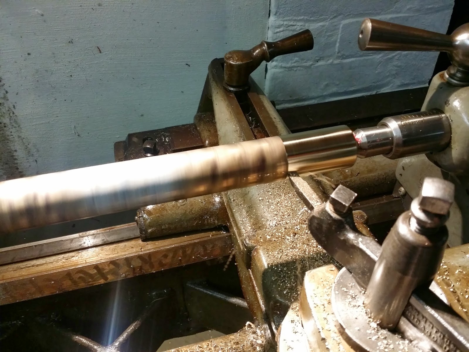
Anyway, here is the one pic I took of the mostly finished pieces:

The left bottom set is for the end of the shifter itself. The other two sets are for the yoke. There is one piece I didn't make, but I am going to see how well this works without that one piece and if it works then I won't bother having to make it right away, which is a good thing.
So if you recall, I left off with these:
 As you can see, those were not drilled and the outside of the shoulders were not faced to size. I hadn't even started the bushings for the shifter, as that was the lowest priority. My shift linkage was so bad at the yoke end, that was what I was needing to focus on, but thankfully I had the time to make them, too.
As far as the process, immediately after I showed up, I found a left hand tool holder and ground a facing tool. The tools I grind (I should take a photo of them sometime) are SHARP. This material seems to prefer a very sharp tool with almost no nose radius and not too much relief on any of the angles. Doing that and tweaking the feed speeds, I can get really decent surface finishes and take off a decent amount (at least for the size of the lathe I am using) per pass. A CNC machine could likely make all of these in the time it takes me to just face one of these things. LOL!
After I got the tool set, I faced the shoulders to size. This dimension isn't exactly precise as the yoke is thin sheetmetal that is pretty flexible. Within 5-10 thou is perfectly acceptable, though I manged to get both sides pretty close to the dimensions I calculated.
Looking at the time, I figured I could knock out the shifter bushings, so I slapped in the round stock, switched tools to the turning tool that I probably should have sharped up a bit but it worked well enough for the little bit of turning I had to do. I got the shafts turned to size, cut the bushings off the bar stock, slapped in the facing tool, faced both sides and then got read to drill and ream.
In production or at least time sensitive work, the thing that nearly always takes the most time is tool changes, so if you can eliminate as many tool changes as possible, especially if you only have one kind of tool holder for what you are doing, you can save a LOT of time. In this case, this basically meant that I center drilled all the pieces first. Dave only has one chuck, so changing the tools in the chuck takes a bunch of time. Granted, this isn't super critical work by any means, so changing the pieces out is perfectly acceptable and preferable to taking the time to mount a tool for every operation change.
So, yeah, I center drilled each piece. I then tried to drill one bushing to the just under the reamer size, but that didn't work too well at all. I read that with this bronze, it helps to grind the bit tip flatter than you would normally find on a general purpose split point bit, but since I didn't want to do that, I just pilot drilled them then got them drilled out to just under the .315" reamer size.
By all accounts, the reaming was supposed to be pretty gnarly, but, well, it wasn't. Dave helped by flooding the reamer with WD40 as we went along. We found a good, chatter free speed to turn the lathe (man, that VFD makes things so easy!) and we finished the holes to size.
In case you didn't know, reamers are for forming very precise and round holes. Drill bits actually don't make very precise or even round holes, usually with poor surface finish to boot. A reamer will make the hole very round and if you aren't rough with it, it will leave an very excellent surface finish for the hole.
We finished up and I had to skedaddle. I didn't get to chamfer the edges, which is slightly annoying but not the end of the world. I can take care of the burrs with a file. These don't have the prettiest finish, but, when these go into production on CNC machines (that's planned), they will be quite the handsome parts.
So that about sums it up for this wall of text. I hope you found some of it interesting, even with only one new picture for the whole post. heh
I was so focused on things that I didn't bother with taking photos of the process, since I took photos the last time and most lathe work is really pretty similar. Turning, facing, drilling, reaming and parting. I'm not doing anything groudbreaking, here.
Anyway, here is the one pic I took of the mostly finished pieces:
The left bottom set is for the end of the shifter itself. The other two sets are for the yoke. There is one piece I didn't make, but I am going to see how well this works without that one piece and if it works then I won't bother having to make it right away, which is a good thing.
So if you recall, I left off with these:
As far as the process, immediately after I showed up, I found a left hand tool holder and ground a facing tool. The tools I grind (I should take a photo of them sometime) are SHARP. This material seems to prefer a very sharp tool with almost no nose radius and not too much relief on any of the angles. Doing that and tweaking the feed speeds, I can get really decent surface finishes and take off a decent amount (at least for the size of the lathe I am using) per pass. A CNC machine could likely make all of these in the time it takes me to just face one of these things. LOL!
After I got the tool set, I faced the shoulders to size. This dimension isn't exactly precise as the yoke is thin sheetmetal that is pretty flexible. Within 5-10 thou is perfectly acceptable, though I manged to get both sides pretty close to the dimensions I calculated.
Looking at the time, I figured I could knock out the shifter bushings, so I slapped in the round stock, switched tools to the turning tool that I probably should have sharped up a bit but it worked well enough for the little bit of turning I had to do. I got the shafts turned to size, cut the bushings off the bar stock, slapped in the facing tool, faced both sides and then got read to drill and ream.
In production or at least time sensitive work, the thing that nearly always takes the most time is tool changes, so if you can eliminate as many tool changes as possible, especially if you only have one kind of tool holder for what you are doing, you can save a LOT of time. In this case, this basically meant that I center drilled all the pieces first. Dave only has one chuck, so changing the tools in the chuck takes a bunch of time. Granted, this isn't super critical work by any means, so changing the pieces out is perfectly acceptable and preferable to taking the time to mount a tool for every operation change.
So, yeah, I center drilled each piece. I then tried to drill one bushing to the just under the reamer size, but that didn't work too well at all. I read that with this bronze, it helps to grind the bit tip flatter than you would normally find on a general purpose split point bit, but since I didn't want to do that, I just pilot drilled them then got them drilled out to just under the .315" reamer size.
By all accounts, the reaming was supposed to be pretty gnarly, but, well, it wasn't. Dave helped by flooding the reamer with WD40 as we went along. We found a good, chatter free speed to turn the lathe (man, that VFD makes things so easy!) and we finished the holes to size.
In case you didn't know, reamers are for forming very precise and round holes. Drill bits actually don't make very precise or even round holes, usually with poor surface finish to boot. A reamer will make the hole very round and if you aren't rough with it, it will leave an very excellent surface finish for the hole.
We finished up and I had to skedaddle. I didn't get to chamfer the edges, which is slightly annoying but not the end of the world. I can take care of the burrs with a file. These don't have the prettiest finish, but, when these go into production on CNC machines (that's planned), they will be quite the handsome parts.
So that about sums it up for this wall of text. I hope you found some of it interesting, even with only one new picture for the whole post. heh